

I have managed to collect quite a few Japanese Playstation games the past year, my favorite probably being Parappa the Rapper.
I picked it up in a BookOff in Ojima, Japan for 108 yen, that’s about 80 cents, Complete in Box with all extras too! Here in Ireland a CiB PAL version goes for about 45 euro! So, I started thinking about picking up an NTSC Playstation 1, problem was that I already have 4 Playstation 1’s!
I used to work in a tiny games shop on Talbot Street called GameZone, it’s long gone now, but people would drop off their PS1, pay 50 or 60 irish pounds, some dude would come pick a batch of PS1’s up and a few days later drop them all off modded. I never took advantage of it at the time and despite being super curious, I never asked what was actually involved.
So, now in 2018, I know it involves a bit of soldering, and that happens to be a skill I’m slowly developing so I was thinking of picking up a modchip, I’ve seen a few on eBay and surprisingly there are still a lot of chips out there for PS1, PS2 and others like GameCube, and they are quite cheap too!
I thought to myself, “wouldn’t it be cool to make my own modchip? It totally would” then, already frustrated with future me trying to figure it out, I went to Github and “modchip playstation” and stumbled across PsNee.
PsNee is a fully Open Source modchip for PS1, it’s stealth, which means it can defeat the DRM on newer PS1 boards and games and, importantly, it runs on Arduino!
It does use Arduino Pro Miniwhich is a bit less user friendly, but not by much. It allows a person to play backups and imports and it does it’s job wonderfully, I’ve played all of my Japanese imports so far and I’ve even burned a few Fan Translations to boot!
So with that, lets get straight into our guide.
Stuff you’ll need:
- PlayStation
- Soldering Iron (any should do)
- Solder (I find nice thin solder the best for stuff like this)
- Soldering Skills
- Some Thin Wire, 30AWG for example
- Sharpie
- Arduino Pro Mini (the PsNee supports other chips, but I’m most familiar with Arduino!)
- FTDI FT232RL for Arduino (this lets you hook the Arduino Mini up to a PC via USB)
- Arduino IDE
- PsNee-V7-Diagram.zip
- PsNee.ino
- A legit game to test.
Preparation:
Take apart PS1

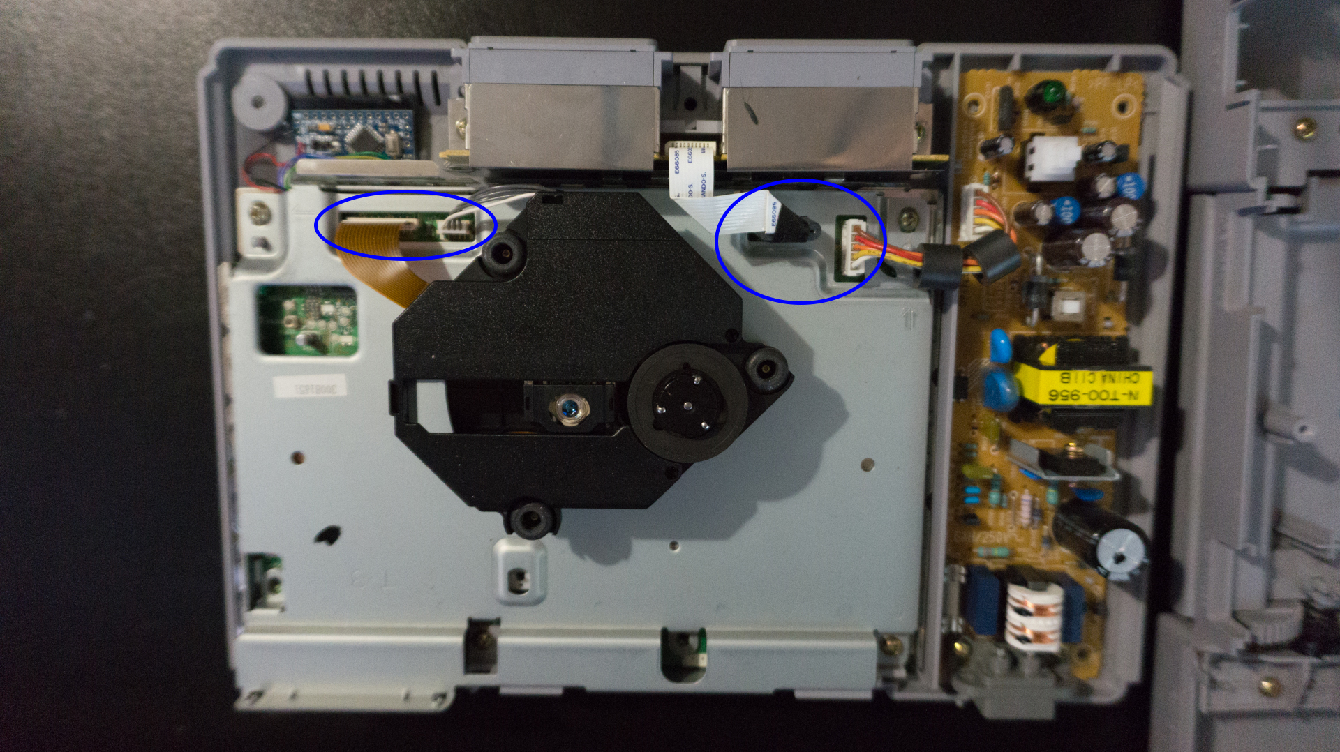
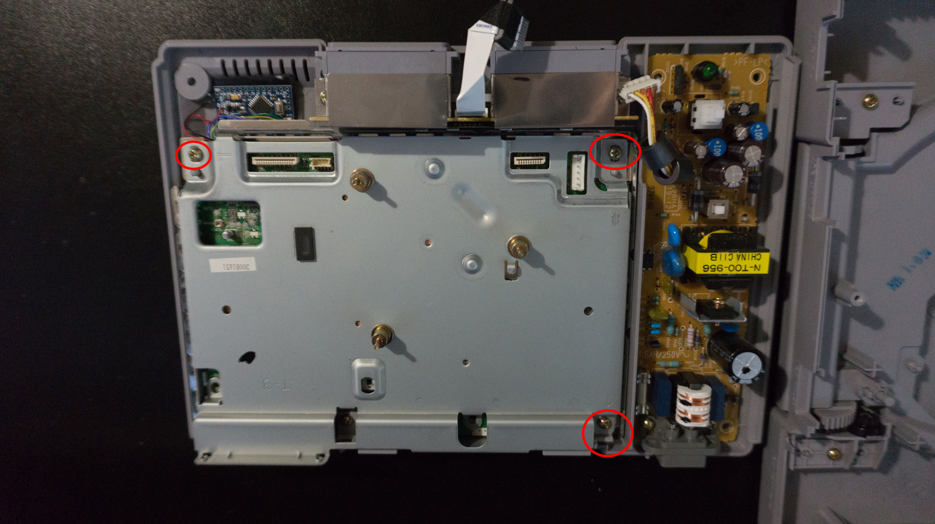
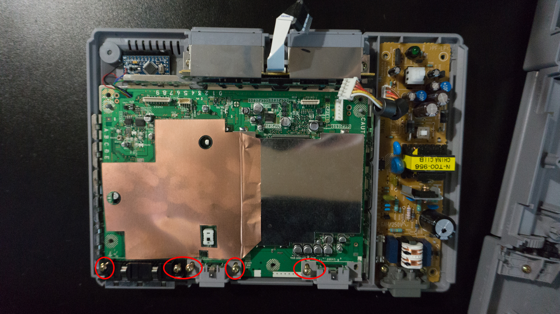
I forgot to take these before I did the mod, so please ignore the Arduino and extra cables!
Identify which board you have
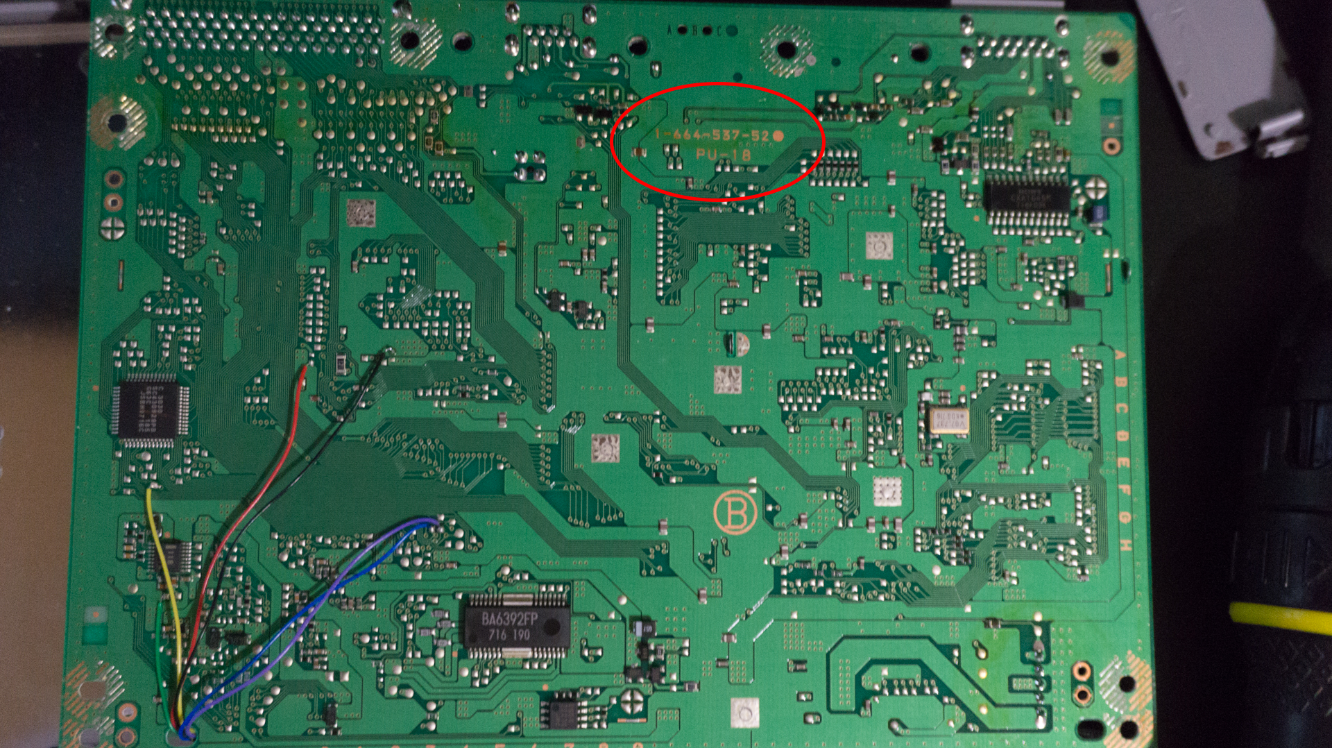
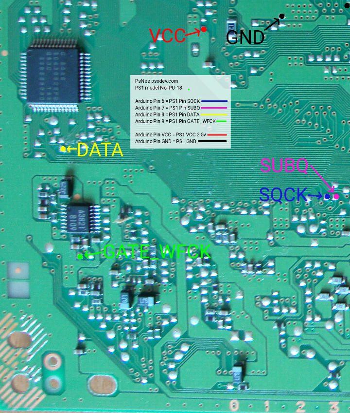
You can see on image below, we’ve flipped the board over and in the red circle on the underside of the motherboard says “PU-18”. This might be in a different location depending on the model,but you can cross reference it with images in the zip file from the PsNee Github project.
Mark where the wires will go
This isn’t required, but the points are SO SMALL that it really doesn’t hurt. There are plenty of times I find all the points I need, then blink and suddenly they are gone again. Take your sharpie, open the diagram that matches your PS1’s board and just mark beside the solder points you will be using with a dot. Make sure you mark the green PCB and not the solder joint.
The diagrams aren’t exactly uniform, but you can use them to locate the solder points you need, here’s the PU-18 points for example, they’ve put color coded dots over each solder point, some diagrams will have the wires soldered on.
!!! PLEASE USE THE ZIP FILE + DIAGRAM FOR THE MOTHERBOARD IN YOUR PS1 !!!
Flash the Arduino
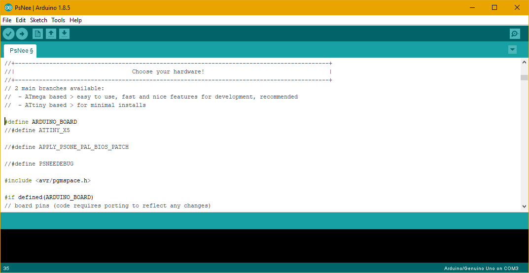
This part is super easy. First, open your Arduino IDE and open the PsNee.ino file.
Scroll down to the part where it says “Choose your hardware!” and uncomment the line that says “#define ARDUINO_BOARD” by deleting the two forward slashes beside it. It should look like:
If you happen to have a PU-41 Motherboard, you must also uncomment “#define APPLY_PSONE_PAL_BIOS_PATCH”
All that’s left to do is to connect the Arduino to your PC and flash the code!
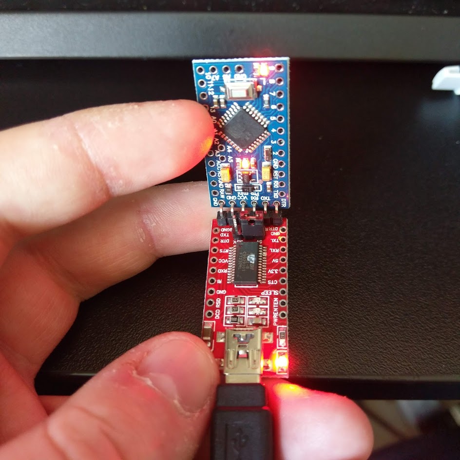
You might now be noticing that the Arduino Pro Mini doesn’t have a USB port on it, well, that’s what the FTDI is for, hook up a usb cable to it and insert it into the Arduino with a bit of force ensuring a good contact like so:
It’ll light up, windows will detect it and you’re almost good to go!
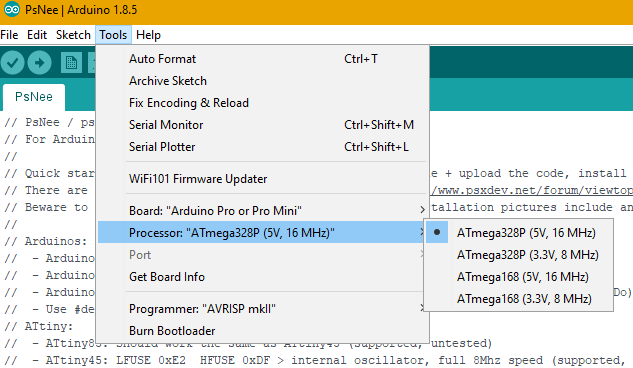
In the Arduino IDE, we need to set the IDE to know which board we are using, so click tools and select the Pro from the Dropdown and select the correct voltage of the Arduino you bought:
Finally, click the check mark to verify the code is good and when it comes back saying everything is ok, this is signified by it saying “Done Compiling” and not throwing any errors, click the arrow beside it to send it over to the Arduino.
Installation:
Solder
WARNING
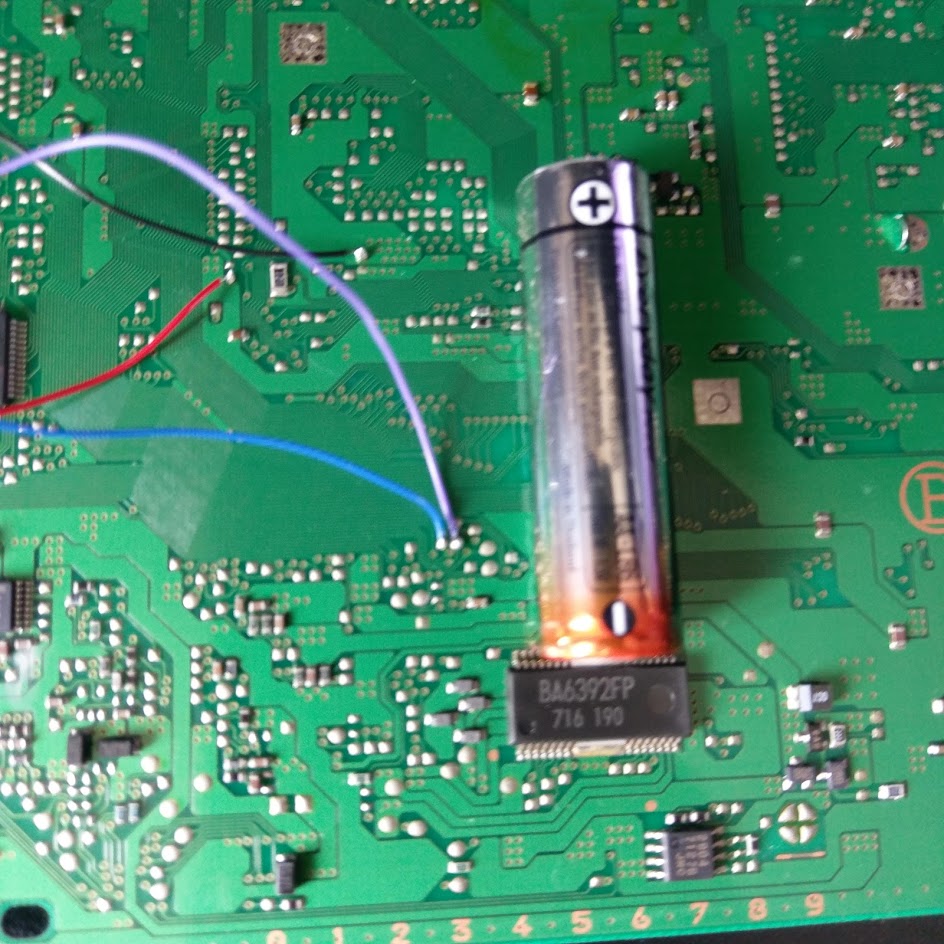
Some of the points on these boards are TINY, if you’re not confident in your soldering skills I’d recommend getting a soldering training kit, or taking apart some old broken piece of tech and just trying to solder wires onto points with that until you’re a bit more confident in your skills. For example here is two points, right next to each other beside a standard AA Battery for scale.
The key is to not panic if you bridge two points, just relax, clean the tip of your iron, and try separate them in the middle, desolder braid is super useful for this, but you also need to be careful with it.
So with that handy warning out of the way, lets get started.
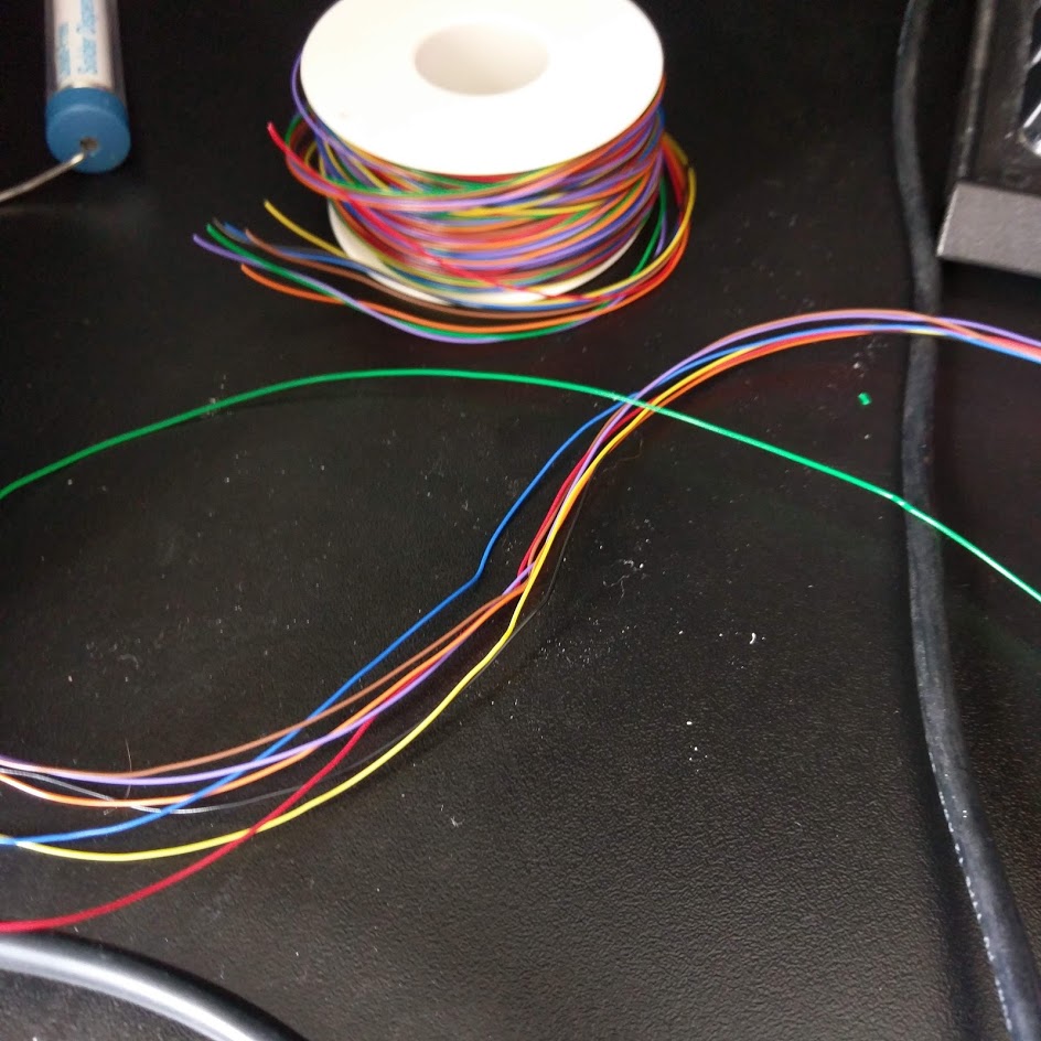
If you can, I find it best to use matching wire colors as the diagrams, if not, it’s no big deal, but maybe use a bit of tape / sticker to label each cable so you can remember what is going where.
What I do is, cut the cables to roughly the length of the PlayStation board, this is more than long enough in most cases and gives you some room left over in case you need it.
Then you start by re-tinning the solder joints you will be using, this is just adding a bit of your own solder to the blob that’s already on the board, there are a few reasons you do this, the main one being that the solder from the factory sometimes melts at much higher temps than the stuff you have at home so mixing some of yours in makes it easier to work with.
Lay your wire on the board, if you cut them as I described above you should have more length than you need, hold one end of the wire in your non dominant hand, the soldering iron in the other.
There’s two trains of thought, either melt the solder joint first, then move the wire into the molten blob while the iron is still touching it, hold it for a sec to let wire heat up, remove the iron and let it set. Or the more “proper” place wire on top of blob and press iron down on wire until heat passes through and melts blob. Either way is fine and works in my book, whatever your preference.
I will say to take EXTRA care here and make sure you are soldering the correct places.
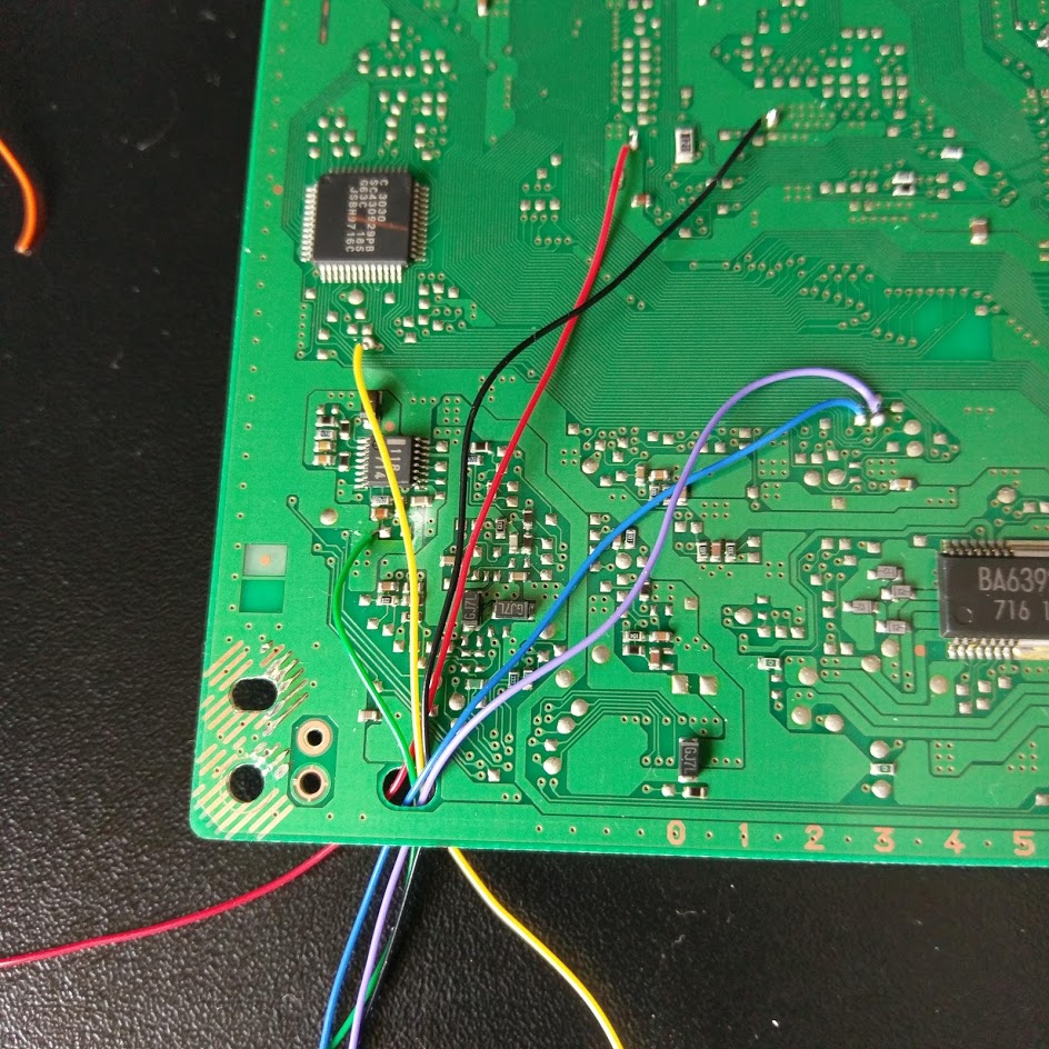
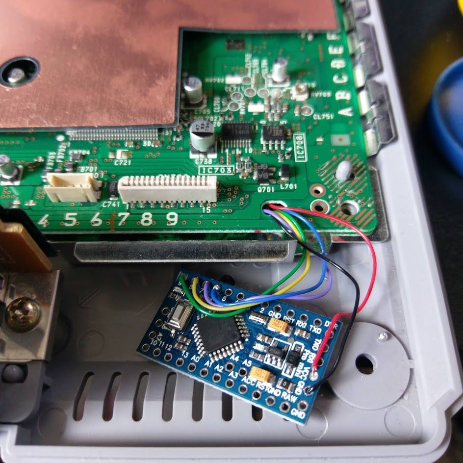
Here’s what mine looked like once I had all wires in place, the PlayStation I modded had a PU-18 Board:
I put the other ends of my wires through any hole in the board for slightly neater cable management. The hole pictured is nicely located for where we will stick the Arduino when we seat it back in the case.
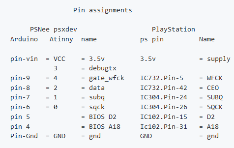
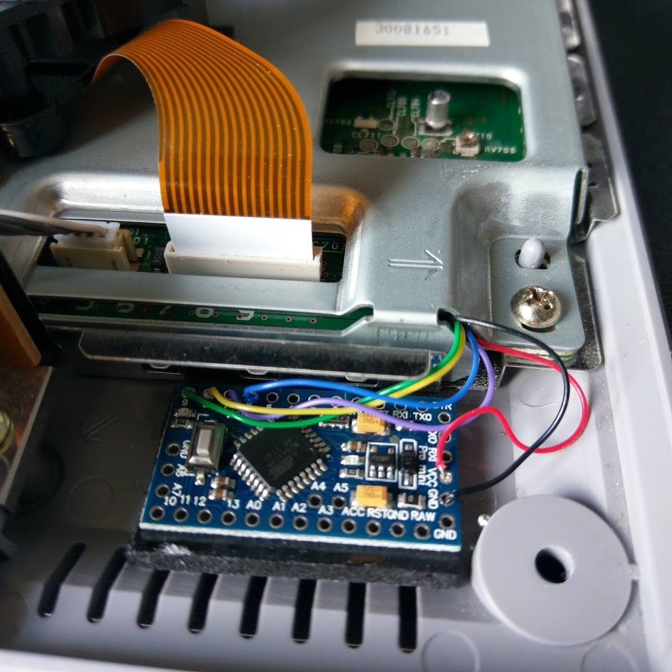
The next step is to solder the cables to the Arduino Pro Mini, we have already flashed the Arduino in a previous step so once this step is complete, we are ready to go. It is important to make sure the correct cables get soldered to the correct spots, there is a table on the PsNee Github page that looks like:
However make sure you reference the actual table as it may change in the future. You can see how mine is soldered here:
With this, we should be ready to test!
Testing
Testing is fairly straight forward, the steps you should follow:
- Test a disc from the consoles original regions.
- Test a disc from any other region.
- Test a burned disc (if you want that sort of thing).
I would again recommend testing against a know working disc, as you want to be absolutely sure any problems that occur are with the chip and not the way the disc was burned.
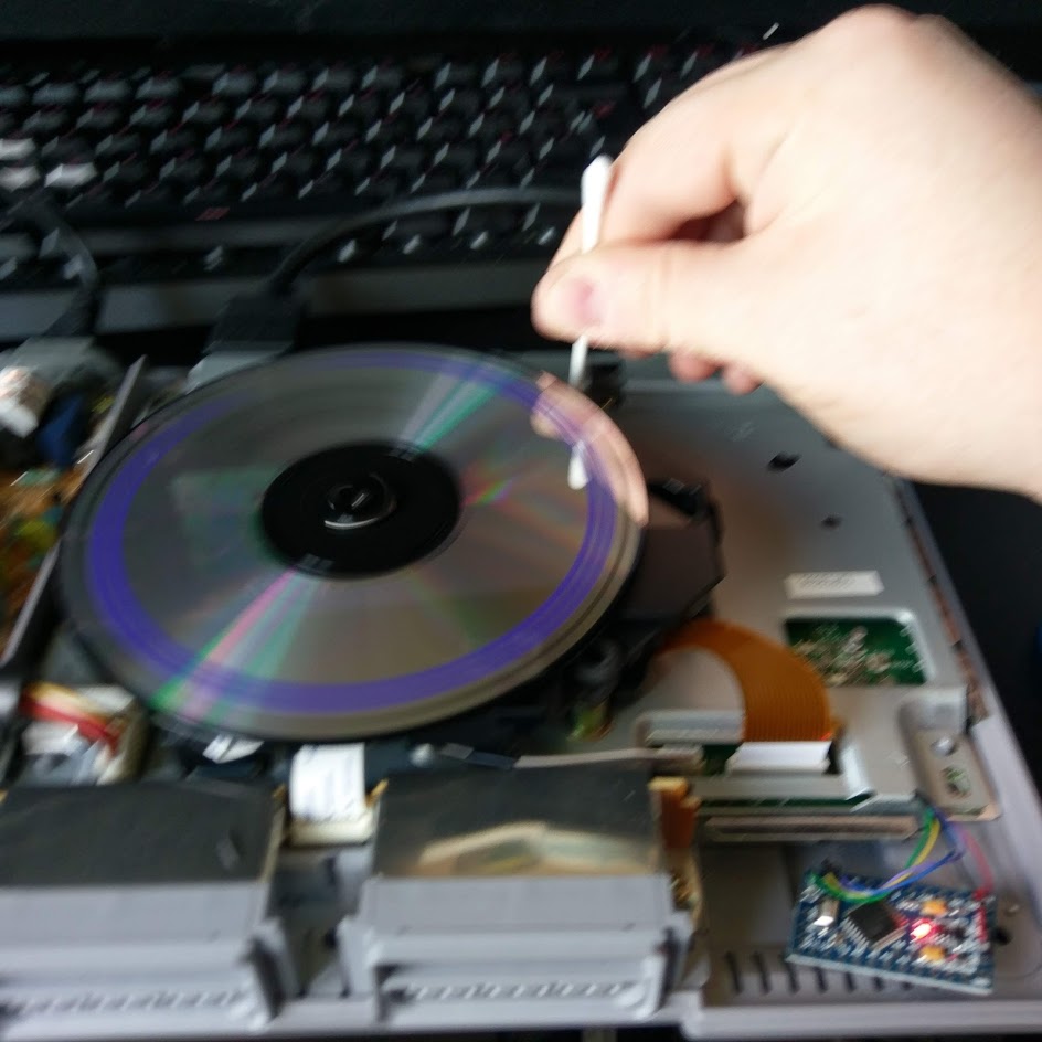
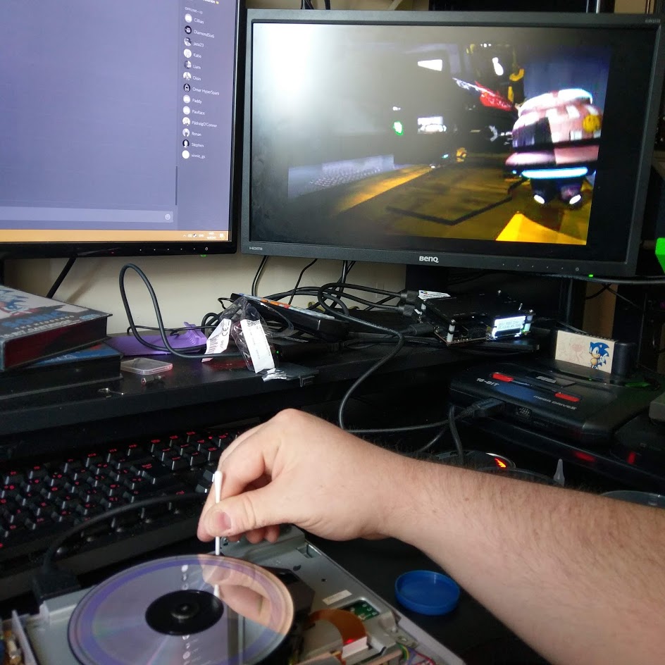
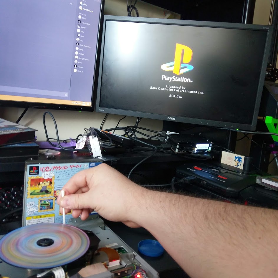
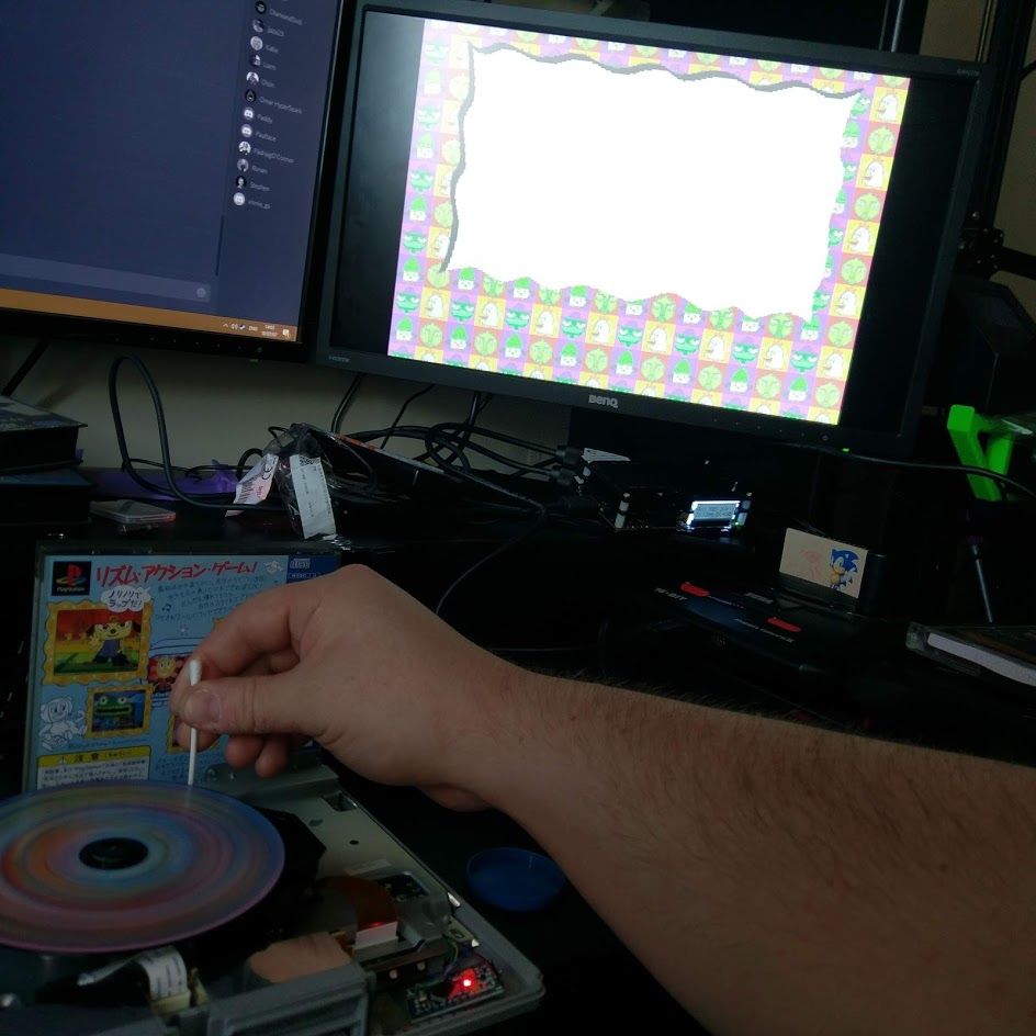
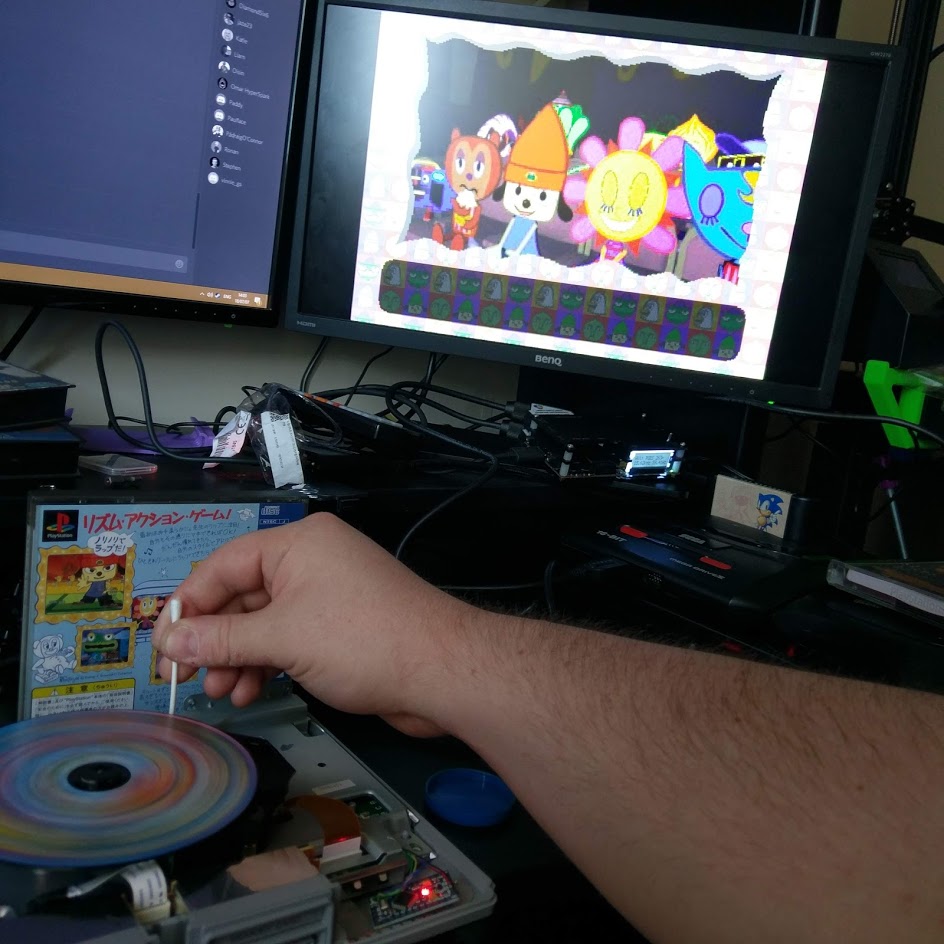
In the gallery above the first two pictures are me testing out my PAL copy of Wipeout, followed by me testing out my Japanese copy of Parappa! I’m using a Cotton Bud / Q-Tip to hold down the “lid closed” button to get it to read.
Hopefully your games boot and all goes well, if not I’m really not sure how to help, I’ve never had this fail, first port of call would be check the Github Issues page and do a quick Google for “PsNee installation issue” or something like that.
Worst case scenario, throw a comment below and I’ll see what I can do, but no guarantees!
Tidy
Once you have it working, we need to fix that Arduino down so it isn’t just loose inside the console.
I happened to have a random piece of rubber, with some sort of prepared glued surface on both sides, probably from a router or some other smart device so I used that, but failing that I don’t see a reason why a Command Strip or something wouldn’t work.
I’d hesitate to hot glue it in as, again, something could potentially go wrong down the line and removing hot glue is 100% zero fun!
Here’s what mine looks like stuck in:
And, well, I guess that is that! It’s a little involved, but you can now say that you made your own PlayStation modchip!
Nice guide. I actually worked in GameZone too around 2000/2001. Haven’t thought about that place in a long time, wonder where Simon is now?!
Last I heard he moved to Australia! Great guy!